We use cookies to make your experience better. To comply with the new e-Privacy directive, we need to ask for your consent to set the cookies. Learn more.


Blend Micro
NOK278.40
In stock
Only 4 left
SKU
RBL-BLE-BLENDMICRO
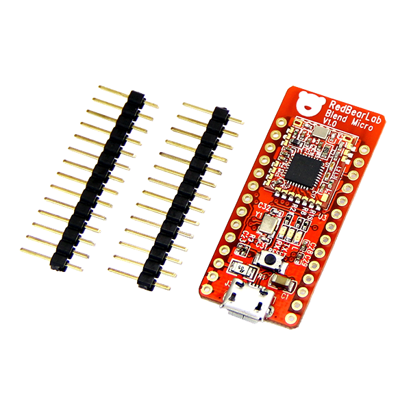
Blend Micro is RedBearLab's first integrated developement board, they have "blend"ed Arduino with Bluetooth 4.0 Low Energy (aka BLE or Bluetooth Smart) into a single board.
It is targeted for makers to develop low power Internet-Of-Things (IoT) projects quickly and easily.
It is targeted for makers to develop low power Internet-Of-Things (IoT) projects quickly and easily.
The micro-controller unit (MCU) is Atmel ATmega32U4 and the BLE chip is Nordic nRF8001.
Blend Micro runs as BLE peripheral role only, it allows BLE central role devices to establish connection with.
Blend Micro runs as BLE peripheral role only, it allows BLE central role devices to establish connection with.
Features
- First BLE + Arduino board under Arduino AtHeart program
- Utilize Nordic Bluetooth Smart SDK for Arduino
- Software development using Arduino IDE or codebender
- Over-the-Air download of sketch to Blend Micro (available soon)
- Work with our free Android App and iOS App
Blend Micro and iOS App
Blend Micro and Android App
Getting Started
We recommend using Codebender, an online development and collaboration platform for all Arduino users, please read to our Quick Start with Codebender to start playing with your Blend Micro in just a few easy steps.
We have also prepared a detail guide Getting Started with Blend Micro to show you how to program your Blend Micro with Arduino IDE.
Description
Blend Micro is our first integrated developement board, we have "blend"ed Arduino with Bluetooth 4.0 Low Energy (aka BLE or Bluetooth Smart) into a single board. It is targeted for makers to develop low power Internet-Of-Things (IoT) projects quickly and easily.
The micro-controller unit (MCU) is Atmel ATmega32U4 and the BLE chip is Nordic nRF8001. Blend Micro runs as BLE peripheral role only, it allows BLE central role devices to establish connection with.
Current supported BLE central devices:
iOS 7 or 8
- iPhone 4s
- iPhone 5/6 (all models)
- iPod touch 5
- iPad 3/4/mini/Air
Android 4.3 or above (4.4 recommended for stability) with Bluetooth 4.0 hardware support
- Nexus 4
- Nexus 5
- Nexus 7
- other compatible Android devices reported by our users
(please report any other Android devices supported)
Windows Phone 8.1
- Nokia Lumia 630
- (please report any other Windows Phone devices supported)
Windows 8.1 with built-in Bluetooth 4.0 or USB dongle
Mac OSX 10.9.2 with built-in Bluetooth 4.0 or USB dongle
Linux with BlueZ 5.1 with built-in Bluetooth 4.0 or USB dongle
How It Works
- The nRF8001 chip communicates with Atmega32U4 through the ACI (Application Controller Interface). The ACI is similar to SPI but not actually works as SPI. SPI is consist of MOSI, MISO, SCK and SS, whereas ACI is consist of MOSI, MISO, SCK, REQN and RDYN.
- Since the nRF8001 chip may receive data anytime even not selected by SPI master (Atmega32U4), so the SS line is not needed.
- For the ACI, data exchange still through MOSI and MISO, and SCK provides the clock generated by master.
- When master wants to request data from BLE Shield, it puts the REQN to low until RDYN line is put to low by BLE Shiled, and then master generates the clock to read out the data. After reading out the data, master will release the REQN and BLE Shield release the RDYN, put them to high.
- If the nRF8001 has data to transmit to master, it will put the RDYN to low to indicate master, even though the master has not requested data and REQN is idle. If the master detectes a low level condition on RDYN, it will put REQN to low and generate the clock to read out the data. After reading out the data, both REQN and RDYN will be put to high. Note that REQN is controlled by master while RDYN is controlled by the nRF8001 chip.
Overclocking
According to the Atmega32U4 specification, this MCU can run at either 8MHz/3.3V or 16MHz/5V. We have desigend the Blend Micro to run at 3.3V only in order to reduce level shifting components and make it as small as possible; it is because the nRF8001 chip only accepts 3.3V. The onboard LDO converts 5V from the USB power source into 3.3V for the board.
Normally, you should set Blend Micro to run at 8 MHz/3.3V. However, if you want to run faster and not concern about the reliabilty (we do not see any issue so far), you can run it as 16 MHz and this is so-call "overclock".


Support
For questions about Nordic Bluetooth low energy SDK for Arduino,
please visit Nordic Developer Zone
All other questions regarding Blend Micro, please visit our Blend Micro Forum
Technical Details
Nordic nRF8001 Bluetooth Low Energy IC
- Support Peripheral (Slave) role operation only – nRF8001 IC limitation.
- Proprietary simple serial interface – Application Controller Interface (ACI).
- Please refer to Nordic’s nRF8001 Product Specification for more details.
Application Controller Interface (ACI)
- The ACI enables an application controller to communicate with nRF8001.
- The physical ACI interface on nRF8001 consists of five pins. All ACI data and exchanges use a standard SPI interface, with nRF8001 using a mode 0 slave interface to the application controller.
- However, nRF8001 does not behave as a pure SPI slave device; nRF8001 can receive new data over-the-air at any time or be busy processing a connection event or new data. Consequently, the traditional CSN signal used to initiate an SPI transaction is replaced by two active low hand-shake signal; RDYN and REQN.
| Signal | Arduino | nRF8001 | Description |
|---|---|---|---|
| MISO | Input | Output | SPI: Master In Slave Out |
| MOSI | Output | Input | SPI: Master Out Slave In |
| SCK | Output | Input | SPI: Serial data Clock |
| REQN | Output | Input | Application controller to nRF8001 handshake signal |
| RDYN | Input | Output | nRF8001 to application controller handshake signal |
Blend Micro Pinout

Specification
| Microcontroller | Atmel ATmega32U4 | ||
| Wireless Chip | Nordic nRF8001 | ||
| Operating Voltage | 3.3V | ||
| Input Voltage | 5V (USB) 3.3-12V (VIN) | ||
| Note: Use either one power source at a time, otherwise you will damage the board. | |||
| Clock Speed | 8MHz | ||
| Connectivity | Bluetooth 4.0 Low Energy micro-USB Serial (TX/RX) I2C SPI | ||
| Flash Memory | 32KB (of which 4 KB used by bootloader) | ||
| SRAM | 2.5KB | ||
| EEPROM | 1KB | ||
| Dimensions | 43.6 x 18.4 x 4.3mm (83 x 58 x 25mm with packaging) | ||
| Weight | 4g (19g with packaging) | ||
| Power Consumption | 2mA (average - using Interrupt mode) | ||
| I/O Pins | 17 | ||
| Pin Functions | 0 | Digital I/O or Serial RX | |
| 1 | Digital I/O or Serial TX | ||
| 2 | Digital I/O or I2C SDA | ||
| 3 | Digital I/O or PWM or I2C SCL | ||
| 4 | Reserved for nRF8001 Reset (Active Low) | ||
| 5 | Digital I/O or PWM | ||
| 6 | Reserved for nRF8001 REQN | ||
| 7 | Reserved for nRF8001 RDYN (Interrupt) | ||
| 8 | Digital I/O or Analog Input (A8) | ||
| 9 | Digital I/O or PWM or Analog Input (A9) | ||
| 10 | Digital I/O or PWM or Analog Input (A10) | ||
| 11 | Digital I/O or PWM | ||
| 12 | Digital I/O or Analog Input (A11) | ||
| 13 | Digital I/O or PWM, also connected to an LED | ||
| A0 | Digital I/O or Analog Input | ||
| A1 | Digital I/O or Analog Input | ||
| A2 | Digital I/O or Analog Input | ||
| A3 | Digital I/O or Analog Input | ||
| A4 | Digital I/O or Analog Input | ||
| A5 | Digital I/O or Analog Input | ||
| MOSI | SPI Master-Output-Slave-Input | ||
| MISO | SPI Master-Input-Slave-Output | ||
| SCK | SPI Clock | ||
| SS | SPI Chip Select or Digital I/O | ||
| Note: SPI is enabled by default for nRF8001. The SS pin is not utilized by nRF8001 and can be used as Digital I/O or for other SPI device. | |||
Write Your Own Review
Please login to comment.
Don't have an account?
Sign Up for free